Building an Electro-Mechanical Power Supply

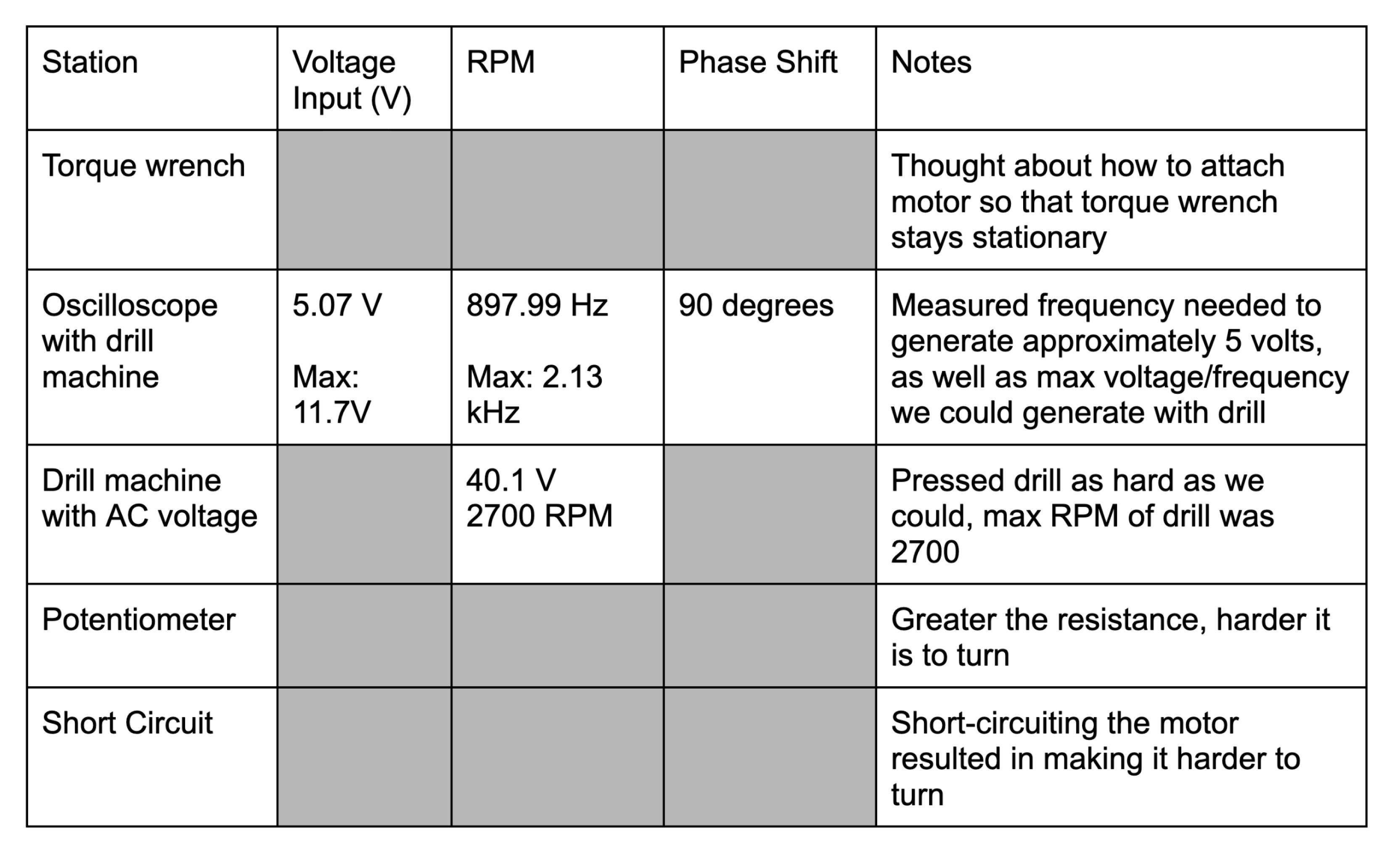
Image of the electro-mechanical system built
In my SYDE 361 - Needs Analysis and Prototyping class, I was presented with an exciting yet daunting challenge: build a hydroelectric device capable of delivering power to a mobile phone. This project provided an opportunity to explore the intersection of mechanical and electrical engineering while also honing my skills in design iteration and problem-solving. Over the course of several months, my team and I tackled everything from generator characterization to circuit design and final assembly. Here’s a detailed look at how this project went from ideation to execution.
Designing the Experiment: Generator Output Characterization
I took charge of designing experiments to understand the power-generating potential of our setup. Specifically, we needed to measure the current output from our generator under various conditions like voltage, RPM, and rotation methods. This was essential for crafting an efficient power circuit that could convert mechanical energy into usable electrical energy for the phone. I developed a detailed experimental plan to measure these parameters during the next lab session, laying the groundwork for what would become the core of our project.

Circuit Design and Connections
The goal of the circuit was to get a 5V output from our input which came from a motor. To achieve the desired output, I utilized a series of two bridge rectifiers, designed to convert AC to DC while boosting the output voltage beyond the input. Here’s a breakdown of each component and its purpose:
Initial Circuit Requirements: Converting AC to DC
Circuit design became my primary focus as the project progressed. The hydroelectric generator produced alternating current (AC) due to its rotating components. However, to power a phone, I needed a stable direct current (DC) output. This meant the circuit had to convert AC to DC, stabilize the voltage, and provide a consistent current. I identified the main requirements as AC to DC conversion using a bridge rectifier, voltage stabilisation with capacitors and current regulation for steady output to the lamp.
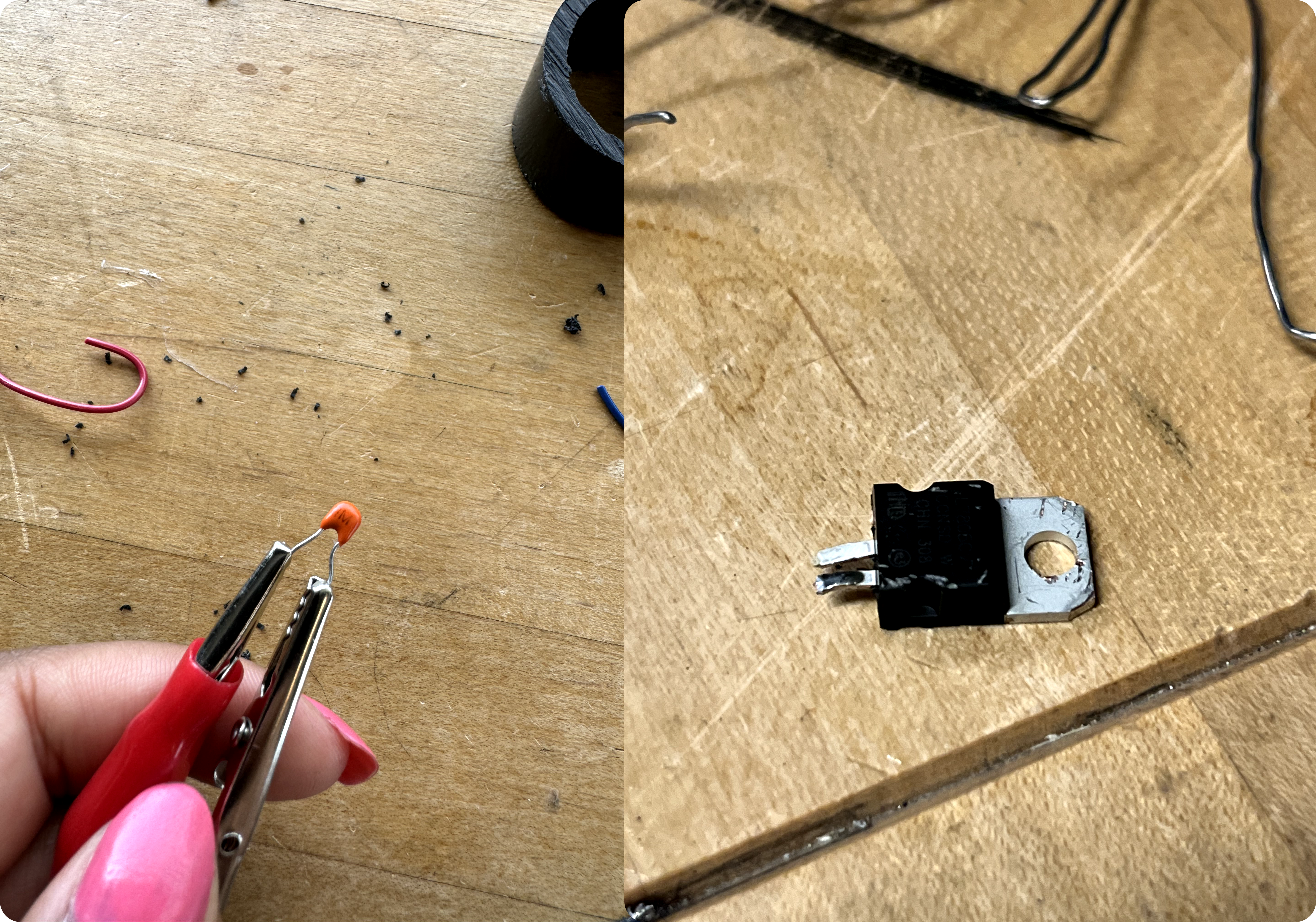
Transitioning the circuit involved some errors which caused damage to some components of the circuit, and led to a less optimal power output when tested. The damage to these components was irreversible, and there was no time to get new parts.
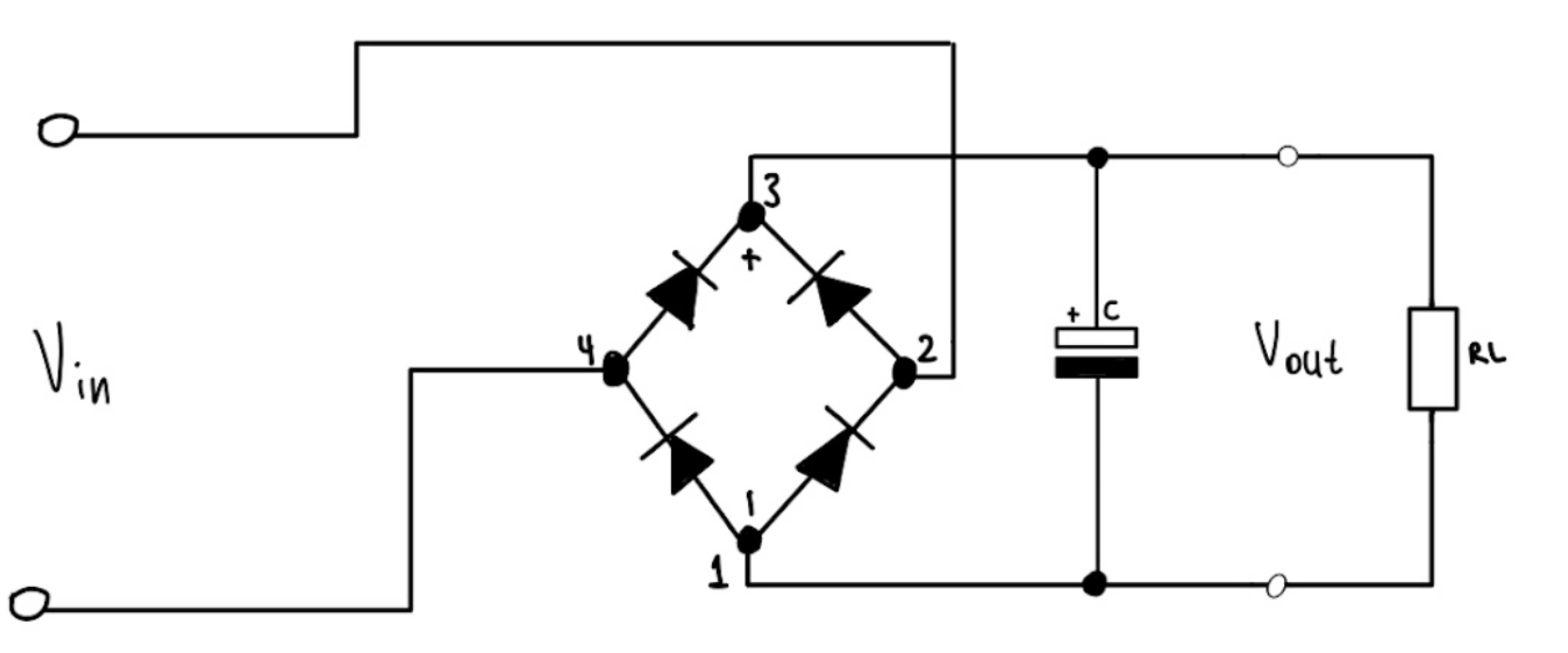
The AC-DC conversion was the circuit’s core function, and we achieved it through a bridge rectifier. A bridge rectifier is a simple circuit that uses four diodes arranged in a bridge configuration to convert AC to DC. Diodes D1 and D3 conducted during the positive half-cycle of AC, allowing current to flow through. Diodes D2 and D4 conducted during the negative half-cycle, keeping the output polarity consistent. The rectifier provided a pulsed DC signal at the output, which required further smoothing.

Initial Sketch of the circuit

Issues starting to occur 😥
Smoothing the Output with Capacitors
Once there was DC output, the next task was smoothing it to prevent fluctuations. I achieved this by adding capacitors in parallel with the output of the bridge rectifier. Capacitors act as reservoirs, storing charge during peaks and releasing it during dips. This minimizes the ripple, providing a steadier voltage output. We used two capacitors in parallel with the bridge rectifier to improve the smoothing effect. Capacitor values were chosen based on our desired output stability; larger values would smooth the output more but require more space.
Adding capacitors significantly improved the voltage stability, making the power output more consistent. However, I noticed that power output dropped when transferring the design from the breadboard to a PCB, highlighting the importance of low-resistance connections in sensitive circuits.
Adjusting Output with Dual Power Sources
To achieve the desired voltage and current for the phone, I found that a single power source wasn’t enough. Connecting two power sources improved the circuit’s performance by providing higher voltage through series connection and increasing available current to the load by distributing the power draw.
This addition was key in stabilizing the circuit’s performance, allowing me to maintain consistent output to the lamp. Initially, I hadn’t accounted for this dual-power need, but testing revealed that two sources provided better performance than a single source alone.
Assembly on PCB and Challenges
After testing on the breadboard, I transferred the circuit to a PCB. This shift introduced new challenges.
I observed that the PCB layout led to a slight power drop, which affected the lamp’s brightness. This was due to increased resistance in the PCB traces compared to the breadboard. The quality of solder joints and connections on the PCB impacted performance. Even minor imperfections in soldering or connections led to noticeable power drops.
Final Testing and Outcomes
The final circuit was functional, and produced power. Through each iteration, this project reinforced my understanding of practical circuit design and the importance of testing, adaptability, and meticulous attention to detail.